
Water control during the construction phase
During construction, when building below the water table or in the presence of significant water flow, temporary water-control devices must be installed. Three main families of techniques are used depending on the needs.
Water collection
Gravity collection is the simplest technique when the water inflow is moderate. It consists of gathering surface or excavation-bottom water into sumps or channels, then evacuating it by pumping towards an outlet (network, watercourse, infiltration).
Typical implementation:
- Creation of sumps at the bottom of the excavation (low-point pits)
- Submersible pumps (from a few m³/h to several tens)
- Peripheral channels to collect runoff
- Discharge tank, control of suspended matter
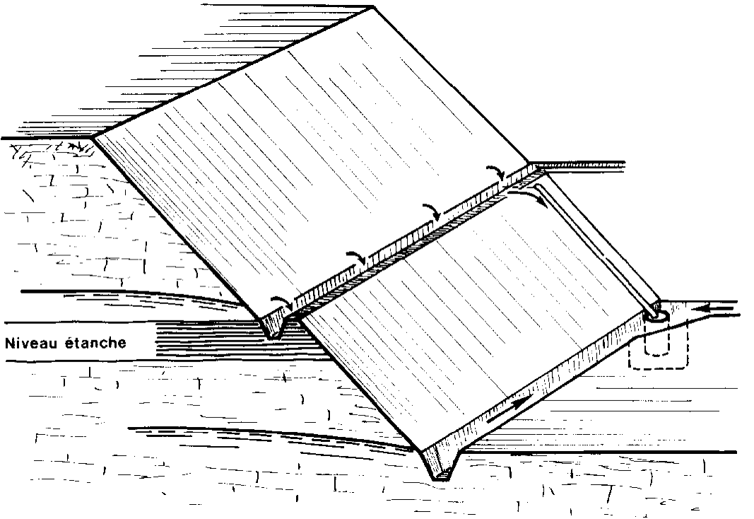
Sub-horizontal drains
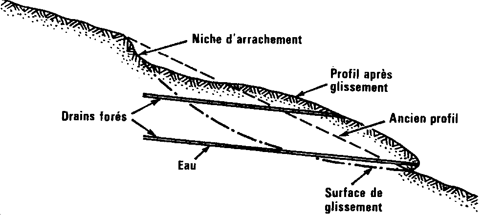
Sub-horizontal drains are drilled into the ground to capture water from a perched water table or a permeable horizon and lower it by gravity without resorting to pumping. They are particularly effective in unstable slopes and hillsides.
Characteristics:
- Drilled from the toe of the slope with a slight upward gradient (~5°)
- Screened casing in PVC or metal
- Typical length 10 to 50 m, sometimes more for large structures
- Spacing of 5 to 20 m depending on the permeability of the ground
- Gravity drainage, no energy required
Widely used for the stabilization of saturated slopes, the drying of sliding hillsides, or in retained walls when one wants to avoid uplift pressures without pumping continuously.
Groundwater lowering
When the expected flow is large or the excavation must be completely dried out, a groundwater lowering system is installed. Several techniques depending on the permeability of the ground and the targeted depth:
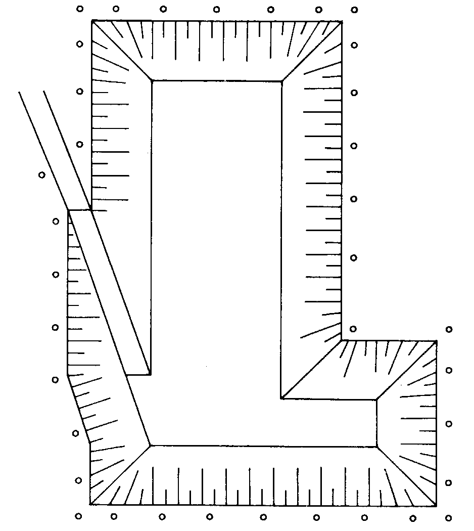
Well-points
For permeable soils (sands, gravels) and moderate lowering (3 to 6 m). A series of filter points (perforated lances of 50-75 mm) is driven at the toe of a bank, connected to a header and drawn by a vacuum pump. Widely used for building excavations in sandy soils.
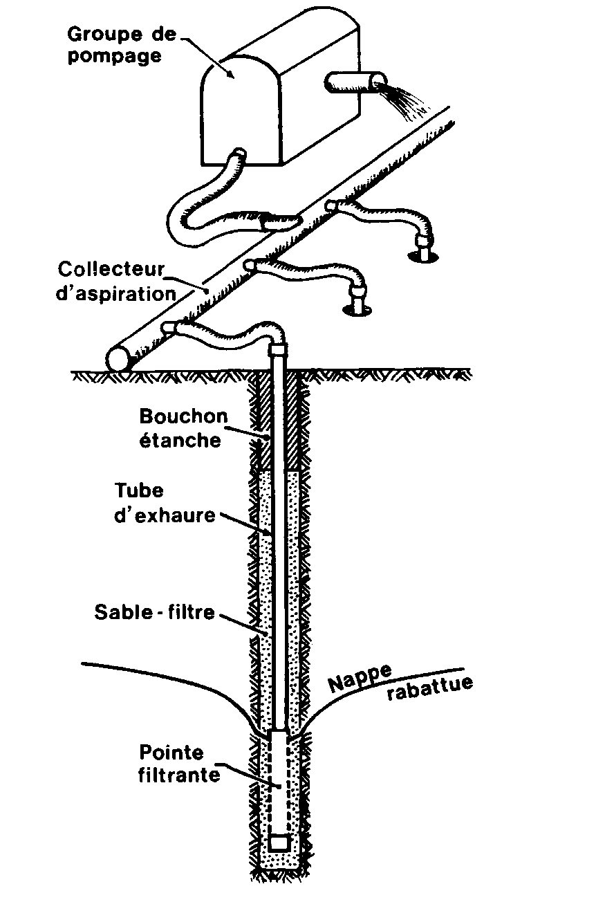
Deep pumping wells
For larger lowering (beyond 6 m) or in less permeable soils. Boreholes fitted with screened casing and submersible pumps, spaced 5 to 20 m around the excavation. In practice, allows the water table to be lowered by several metres.
Precautions
- Settlement by hydraulic consolidation of nearby compressible ground → piezometric and topographic monitoring of neighbouring structures
- Washout of fines which can loosen the ground and cause subsidence
- Environmental impact on the aquifers, neighbouring wells, aquatic environments (Water Act regulations)
- Management of discharge water (release, possible treatment of laden water)
The design relies on the prior estimation of the flow rate (formulas of the Forchheimer, Theis, Jacob type) from the measured hydrogeological parameters (Lefranc tests, preliminary pumping test).